IMU Image Synchronization
Introduction
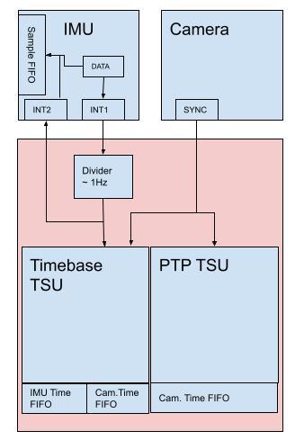
The IMU and the camera sync are synchronized using an internal timing structure with a built-in FIFO, called the Timebase TSU (Time Stamping Unit).
System Design
The Timebase TSU maintains two independent FIFOs.
IMU Time FIFO
Camera Time Sync FIFO
The Timebase TSU is responsible for timestamping the occurrence of the divider signal, and is responsible for timestamping the camera sync signal.
The same Timebase TSU signal from the IMU is added to the IMU’s internal FIFO which can be read later by software and used to correlate the Timebase timestamp with the data in the IMU. The Camera sync signal is also internally routed to the Ethernet MAC PTP TSU. Which allows software to establish a relationship between the IMU Time and the PTP Time.

Camera Timing
The camera sync signal with respect to the camera integration time, is approximately 0.1 ms behind the previous frames integration as shown below, and is constant. The sync signal is then synchronized with PTP to within 12us. The below two figures show the relationship between; integration time, camera sync signal, and camera read out.

The sync signal occurs before the camera integration, please see the below diagram, taking into account the relationship between the sync signal and the camera integration.

To understand when the image was taken, the frame rate at which the camera is operating is required.
However the frame rate reported by utilities like libmultisense is likely not the Operational frame rate of the camera. The operational frame rates based on the requested frame rates are listed below, see Operation FPS Table.
Note: This applies only to the stereo monochrome imagers, and to the first line of the color imager (Rolling Shutter).
IMU Timing
The IMU timestamps are accurate to within 1us.
To determine the time of individual samples, the 1Hz IMU signal which is Timebase timestamped, is linearly interpolated, based on the time of the Timebase TSU timestamp and the amount of samples received in between two distinct FIFO timestamp readings.
Operational FPS Table
The values below are based on v5.19 firmware, unless stated otherwise.
This table can be temporarily added to the user’s source code to determine the operational frame rate of the camera, based on the requested frame rate. However, in the future firmware releases, this information will be provided by the image header as a field, which can be accessed in the user’s program.
Requested FPS |
Operational FPS |
Note |
|---|---|---|
01 |
30 |
|
02 |
30 |
|
03 |
30 |
|
04 |
28 |
|
05 |
30 |
|
06 |
30 |
|
07 |
28 |
|
08 |
32 |
|
09 |
27 |
|
10 |
30 |
|
11 |
33 |
|
12 |
24 |
|
13 |
26 |
|
14 |
28 |
|
15 |
30 |
|
16 |
32 |
|
17 |
34 |
In v5.21 and later [17,17] |
18 |
18 |
|
19 |
19 |
|
20 |
20 |
|
21 |
21 |
|
22 |
22 |
|
23 |
23 |
|
24 |
24 |
|
25 |
25 |
|
26 |
26 |
|
27 |
27 |
|
28 |
28 |
|
29 |
29 |
|
30 |
30 |