Mounting and Installation Guidelines
Overview
For the most part, installing a MultiSense stereo camera is straightforward: Point it where you want to look and bolt it on. The below discussion is intended for those who want to squeeze every last bit of performance out of their stereo cameras.
Camera Perspective Considerations
When considering where to mount the camera, the first and most obvious consideration is what the camera needs to see. A useful corollary to “what does the camera need to see” is the opposite question “What am I looking at that I don’t need to see?” Compared to mounting monocular cameras, the problem is three times more difficult for stereo cameras: both sides of a stereo camera need to see an object for the stereo camera to compute distance to that object, and for each camera we need not only consider the angular direction to to the object, but also the distance to the object.
The stereo camera’s output is a disparity image, which in the case of MultiSense is the left camera’s image colored by how close things are instead of by how bright they are. When mounting the camera consider that the origin of the 3D scene will be given from the left camera’s perspective. Despite this asymmetry, stereo cameras are usually mounted symmetrically on vehicles and equipment. It is not just for aesthetic reasons: the scene presented in the left camera’s frame consists of distance measurements to things that both cameras can see, so both cameras should be placed close to the center of what the camera is trying to see.
Obstructions
Obstructions are doubly bad in stereo cameras when compared with monocular cameras because any obstruction will be viewed from two perspectives. Since the camera needs to be able to see an object from both perspectives to compute the distance to that object, any obstruction obscures depth measurements in two places, the left camera’s perspective and the right camera’s perspective. Obstructions create a “shadowing” effect in the disparity image which is what the left camera can see but the right camera cannot.
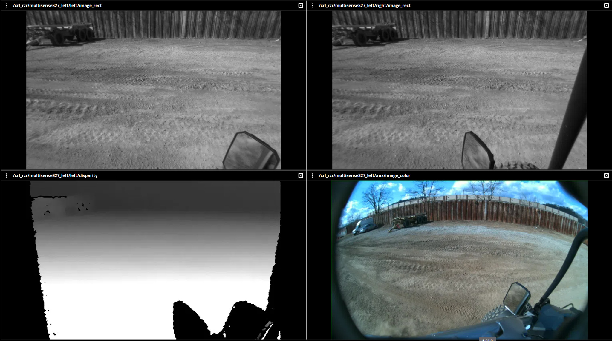
In this scene, the vehicle’s mirror is very close to the camera and is blocking very different parts of the left and right cameras’ fields of view. A permanent butterfly shape of no-disparity values appears in the bottom right corner of the disparity image. The vehicle’s roll cage blocks the right part of the right camera’s field of view, but not the left, resulting in a shadow in the right camera’s disparity image.
Importantly, stereo cameras using semi-global matching (including MultiSense stereo cameras) exhibit a hard minimum distance. For technical reasons, the cameras do not attempt to measure the distance to objects within this minimum distance, but will attempt to match these objects with objects that are farther away, resulting in spurious results in the region of the obstruction. Try to avoid obstructions within this minimum distance because they have a high likelihood of generating false matches, depending on the scene behind the objects. For the same reason, avoid obstructions that can only be seen in the left or right camera’s field of view and not in the other camera’s field of view. If such obstructions are unavoidable, be sure to mask them out of the disparity image when post-processing the camera’s output.
Obscurants (Dust, fog, smoke, etc.)
In many applications that use stereo cameras, obscurants (dust, rain, snow, fog, smoke, etc.) are an unavoidable part of the application, and this is indeed the reason for using stereo cameras instead of other sensing modalities. However, obscurants do affect the stereo camera’s measurements. When an obscurant is in the field of view, three things can happen:
The camera detects the distance to an object through the obscurant
The camera detects nothing
The camera detects the distance to the obscurant
For most applications, the first of these is the most desirable and the last is the least.
Detecting through the obscurant
The circumstances where the camera will detect through the obscurant are when the object behind the obscurant is brighter than the obscurant itself and the contrast of the object beyond the obscurant exceeds the contrast in the obscurant. An important way to ensure that the scene behind the obscurant is brighter than the obscurant itself is to try to move the predominant light source beyond the obscurant. When lit with sunlight, this is relatively easy, but when the application provides the light from nearly the perspective of the camera, the light source should be moved to a location where the obscurant is the most sparse. Try not to illuminate the obscurant! It makes the obscurant harder to see through. Consider that fog lights on cars are mounted low where the heat of the road usually reduces the fog’s density. This is to allow the light to travel past the fog on the outbound path and illuminate whatever is behind the fog more brightly than the fog itself. It is easiest to detect through an obscurant when the obscurant is sparse. Most obscurants diffuse into the air with an inverse square from the distance of the source of the obscurant. This means that moving the camera away from the source of an obscurant even a little bit can have a significant effect on its ability to see through the obscurant.
In scenes where there is little or no ambient illumination, Carnegie Robotics’ thermal stereo cameras outperform penetrating through dust and fog when compared to visible spectrum cameras with co-located light sources.

Detecting nothing
As an obscurant becomes denser, the camera becomes more likely to detect nothing than the object behind the obscurant or the obscurant itself. This is particularly true if the stereo post filter strength is turned up quite high. It is common when the obscurant has low texture, which is most common for fog and well-suspended (small particle) obscurants.

Detecting the obscurant itself
It is rare that a stereo camera will detect an obscurant, but it can happen. It usually happens when the obscurant is very dense and billowing, which makes it have some visual texture for the stereo matching algorithm to cue off of. If billowing obscurants are expected, and it is undesirable to detect the obscurant, try to move the camera farther from the source of the obscurant.

Detecting through smoke
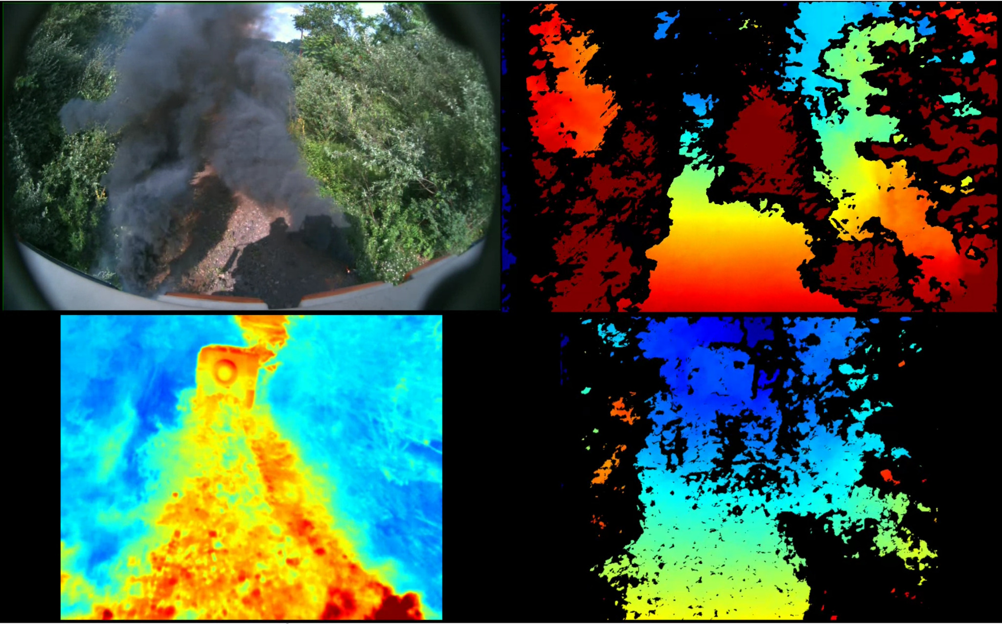
With the exception of specially-formulated, military-grade smokescreen smokes, long-wave infrared light can penetrate smoke because the majority of the particles are not large enough to reflect the long light waves. In this case, Carnegie Robotics’ thermal stereo cameras are an excellent option to penetrate smoke as if it weren’t there.
Field of View Angle
The standard method of measuring how much a camera can see is by measuring its field of view with an angle. This is the angle that the camera would have to rotate for a stationary object to travel from one edge of the image to the opposite edge of the image, when rotated about the lens’s apparent aperture. Consider this angle the angle of the peak of a pyramid with a rectangular base. All things within that pyramid are visible to the camera.
MultiSense specification sheets quote the fields of view of our cameras. These fields of view are of the raw image, not the rectified image, which is a necessarily cropped field of view for the purposes of performing the stereo computation in real time. Solid models estimating the fields of view are available upon request. These fields of view models are not perfect pyramids as described in the paragraph above because they model the barrel distortion that some MultiSense cameras suffer from.
Mounting for Great Stereo Quality
When considering where to mount your MultiSense camera there are two things that strongly affect the quality of the data that you will get:
The geometry of the scene
The illumination of the scene
The Geometry of the Scene
Stereo cameras perform their best when the objects they are trying to measure are normal to the direction of view–and conversely, they perform less well when trying to measure surfaces parallel to the direction of view. There are two reasons for these differences
Surfaces normal to the direction cover a large fraction of the field of view, whereas those parallel to the direction of view cover a small fraction of the field of view.
The difference in perspective between the left and right cameras affects the appearance of the normal surface hardly at all, while surfaces nearly parallel to the direction of view can be completely different-looking from the two perspectives, which confuses the stereo matching algorithm more easily.
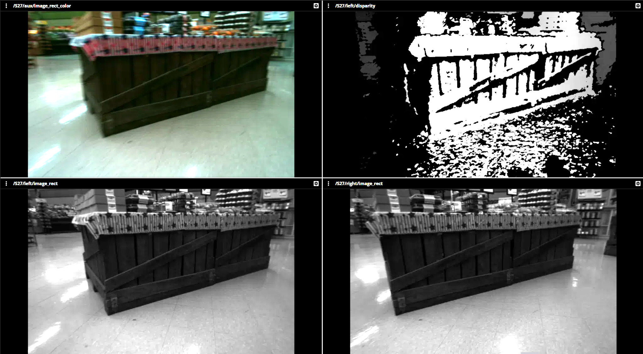
Consider the wooden crates in this figure. When viewed directly the stereo matching algorithm has little trouble identifying the crates and computing the distance to them, which it transmits with the disparity image in the upper right corner of the figure.
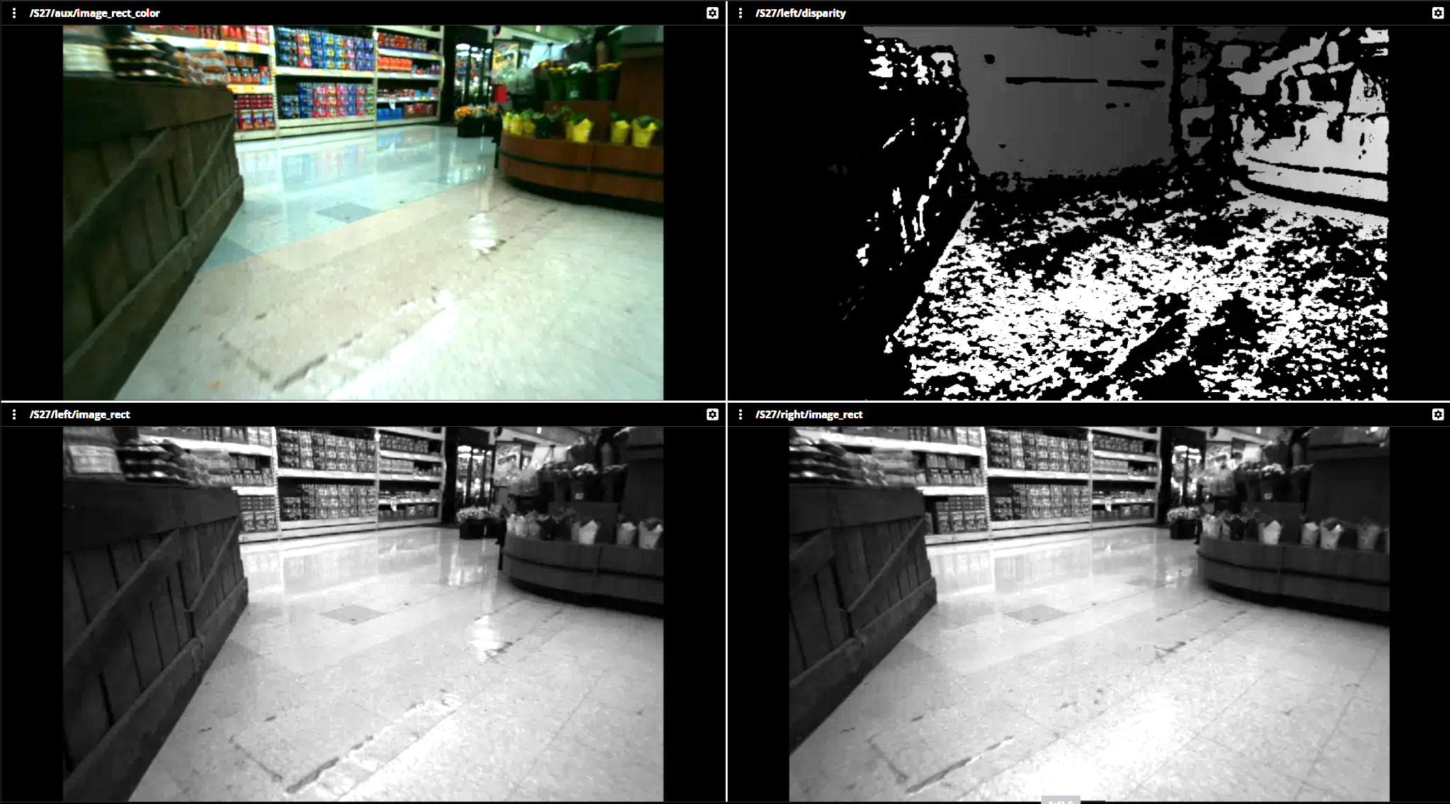
In this figure the wooden crates are viewed obliquely, and the stereo matching algorithm has some difficulty identifying the crates because they appear so different in the two images.
Many practical scenes have one or more large flat surfaces that the camera is intending to model. Consider the following applications:
Modeling the interior of a box with no lid from above: the bottom of the box will appear clearly in the stereo camera, but the edges of the box will be very difficult for the camera to model.
Modeling the ground surface in a self-driving application. Placing the camera near the ground will make it appear very different in the left and right images, resulting in poor performance from the matching algorithm.
Example:
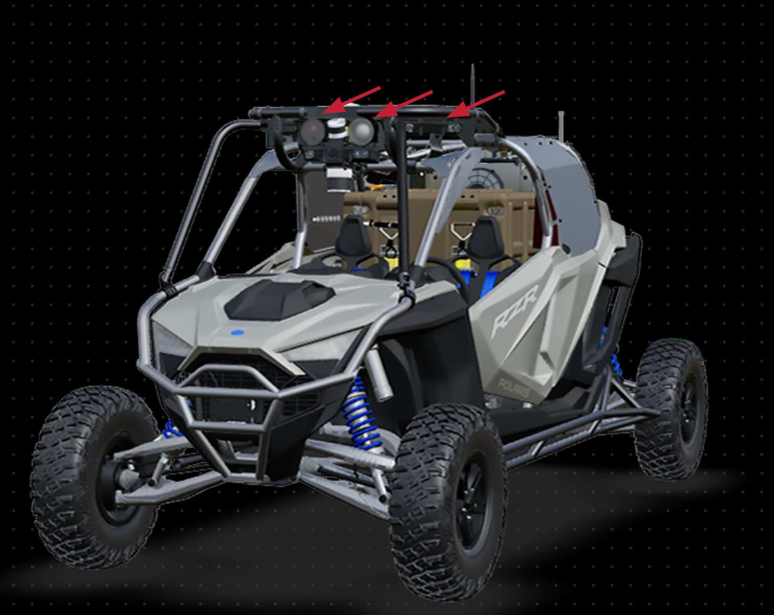
Carnegie Robotics’ Stallion autonomy development platform has four stereo cameras, along with several other cameras and other sensors. All cameras are mounted as high on the chassis as possible to ensure that they have a clear view of the ground in front of the vehicle, and are closer to normal with the ground. This allows the cameras to model the ground accurately as well as to see into “negative obstacles” more readily.
The Illumination of the Scene
Carnegie Robotics’ MultiSense stereo cameras use global shutter image sensors, which means that they perform with almost no motion artifacts in highly dynamic environments. However, the global shutter sensors have one or several extra transistors at the pixel level compared, which reduces the full well capacity of the pixel, resulting in a lower total dynamic range of the sensor. It is therefore important to consider the scene’s illumination when considering mounting options for MultiSense cameras.
Scene illumination comes in two broad types:
Direct illumination: this is lighting that is coming directly from a light source in the scene into the camera’s lens, or is reflecting specularly off a shiny surface into the camera’s lens.
Indirect illumination: this is lighting that reflects off of diffuse surfaces before entering the lens of the camera.
Although it is difficult to eliminate direct illumination in many scenes, direct illumination greatly increases the dynamic range of the image, and the camera has to make a decision about what part of the image to expose properly. Generally, the default settings make the image darker because fully saturated pixels (those that are measuring as much illumination as they possibly can given the gain and exposure settings the camera used for that image) contain no visual texture for the stereo matching algorithm to operate on, whereas the dark parts of the scene maintain some texture that the algorithm is sensitive to for quite some time after they appear visually uniform.
To reduce the amount of direct illumination in the scene, it can be helpful to point the camera away form known light sources, where possible. A classic example: keep the amount of sky visible in the camera to a minimum unless you’re trying to see things in the sky. Another way to keep the stereo camera
Scene Flow and Motion Blur
When most visible-spectrum cameras operate in the low light conditions, they integrate the photons into an electrical signal for a longer period of time. This increases the signal of the photoelectric effect in the pixel, which results in simply more signal. The signal then doesn’t need to be amplified as much, which means there is less noise in the image. However when scenes are moving, the crispest image is created by having a short integration time so that objects in the scene don’t slide from one pixel to the next during the exposure. Both motion blur and amplification noise are detrimental to the stereo matching algorithm’s performance, but motion blur is mostly detrimental to the camera’s performance /in the direction of the baseline of the camera /(horizontally).
If the camera is intended to operate in low-light conditions, an important mounting consideration is the dominant motion through the image. If at all possible, the camera should be oriented with the motion through the image traveling in the vertical direction, and not horizontal.
Thermal Management Considerations
There are no special requirements to remove heat from MultiSense cameras in-application. However, the sensors, like all image sensors, suffer from a phenomenon called dark current noise. Dark current noise appears as random speckling in the image when the sensor is hot, and is primarily noticeable in dark environments. If the cameras are intended to operate in dark environments, a small amount of airflow, or at least some access to fresh air, is encouraged to help limit the amount of dark noise the sensors exhibit.
Mounting Behind a Window
Some applications require the MultiSense stereo camera to be mounted behind a window. Windows are often used for protection, aesthetic purposes, or to take advantage of existing cleaning systems like windshield wipers. Introducing windows into the optical stack does, however, create an extra pair of surfaces (the outside of the window and the inside of the window) that can generate lens flares and stray light artifacts in the image. The primary concern is reflections off the inside of the glass. There are two mitigations:
Ensure that there are no light can enter between the window and the camera lens, except through the window
Ensure that objects near the camera lens are matte black or another dark matte color to reduce the number of reflections.
If possible, include right-angle stair steps in the design. The concave right angles ensure that light reflected off the surfaces travels back in the direction it came from.
Usually, cameras are installed against windows with a black shroud to prevent light from entering and reflecting.
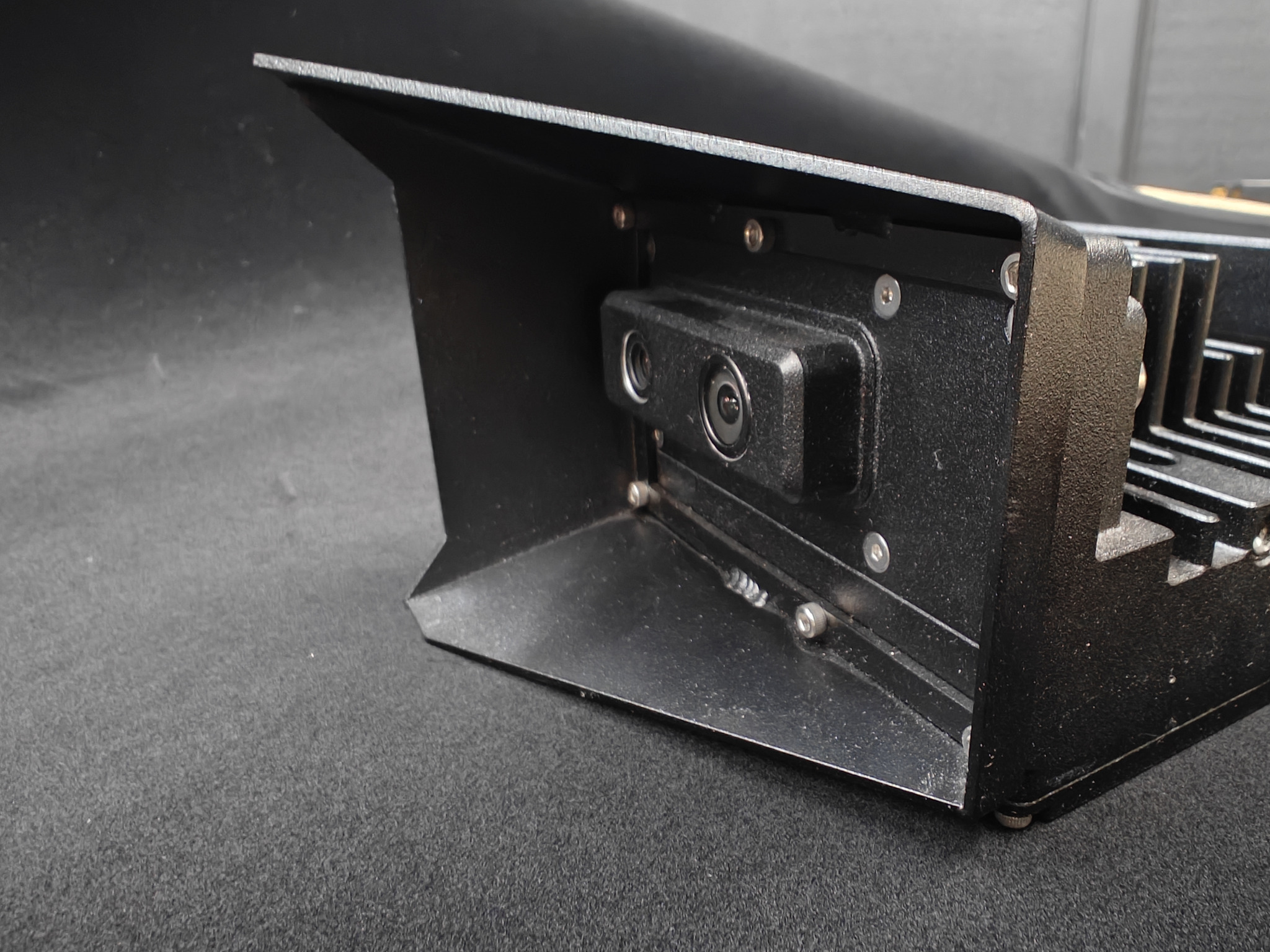
A custom built camera for mounting behind a glass window that exhibits a custom-built shroud for reducing stray light artifacts off the back of the glass.
Some applications that operate in a highly abrasive environment will use abrasion resistant sapphire windows. When selecting a sapphire window, consider also the birefringence of sapphire (that is, its index of refraction is different in one direction than in the other within the crystalline structure). For thick sapphire windows cut at an angle with respect to the crystalline structure, the sapphire may double the image. This can be prevented by specifying windows cut in the C-axis orientation.
Cleanliness Considerations
Optical surfaces are carefully curved and have carefully controlled indices of refraction along their surfaces to focus the light and to reduce reflections. When these surfaces are changed by water, oil, or other transparent substances, the focus point of the lens changes and the image appears blurry. Similarly, specks of dirt or an accumulation of dust on the lens surface can cause the image to blur and the light not to travel along the intended path.
As specs of dirt get closer to the aperture of the lens, they become less and less focused. Carnegie Robotics has elected not to include a window in front of the lens on the S30 and S27 because this pushes the accumulation point for dirt and debris closer to the aperture, and therefore more out-of-focus. Although the cameras will continue to operate with dirt and debris on the lens, the operation will be degraded as the image becomes more blurry.
To keep the lenses as clean as possible, it helps to mount the cameras as far as practicable from sources of dirt that could stick to the lens. The S27 and S30 are equipped with lens hoods that prevent dirt from hitting the lens when that dirt comes from directions outside of the field of view. This significantly reduces the amount of dirt that accumulates on the lenses when in a dirty environment, and it can be taken advantage of simply by pointing the camera so that the field sources of dirt, debris, water, and oil are outside of the field of view of the cameras. For self-driving vehicles operating in dirty or muddy environments, the use of mud flaps, fenders, and similar dirt-blocking devices has a surprisingly positive effect on the performance of the cameras.
The S30 and S27 can be pressure washed or sprayed down to clean them. In environments where the debris is hard or gritty (such as sandy environments, quarries, hard rock mines, and the like) spraying water on the lenses is strongly preferable to wiping with a soft cloth, as the grit can scratch the lens surface. Minor scratches may not be immediately visible, but they do result in more internal reflections in the lens and poorer performance of the objective element’s anti-reflective coating.
For applications where cleaning the lenses is not practical, Carnegie Robotics offers an optional spray nozzle kit that is compatible with standard automotive washer fluid systems (available on S27 and S30). The kit replaces the camera’s lens hoods and allows the user to rinse the lenses when necessary.
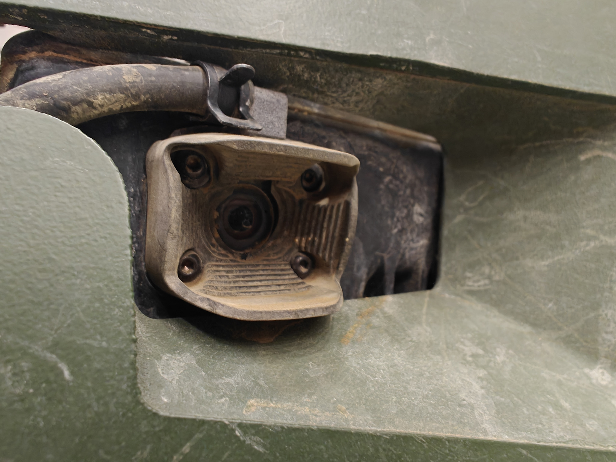
An S27’s right lens equipped with the washer nozzle system. This unit has been integrated into an autonomous vehicle designed for muddy environments.
Mount Stiffness and Vibration Isolation
For most applications, the stereo cameras should be bolted directly to the application vehicle or machinery. However, some applications intend to mount the camera some distance away from the vehicle on an arm or other flexible structure. This section contains some insights into constructing mounts for the stereo cameras.
To reduce unnecessary motion blur in the image, the mounts should be relatively stiff. Mounts with natural frequencies approximately equal to or below the frame rate of the camera will produce significant blurring in the image and the appearance of the scene moving around. It is therefore recommended to keep the mount stiffness (with camera installed) above 30Hz, with a target closer to 100 Hz or higher. Try to keep vibration displacement amplitudes below 1/10,000 of the scene scale: i.e., when looking at objects 10m away, 1mm vibrations are noticeable. Rotational modes of vibration are considerably more noticeable than translational modes. Note that the stereo camera’s pixels subtend less than 3 arc-minutes of angle (1/20th of a degree). Rotational vibrations of 3 arc-minutes are extremely clear in the image, and those half that amplitude are still detectable.
When mounting the camera on isolators, it is important to remember that the mass distribution in MultiSense cameras is not equal across all the mounting points. Therefore, if equal stiffness isolators are used in all mounting locations, significant rotational modes will result.