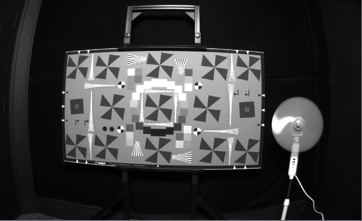
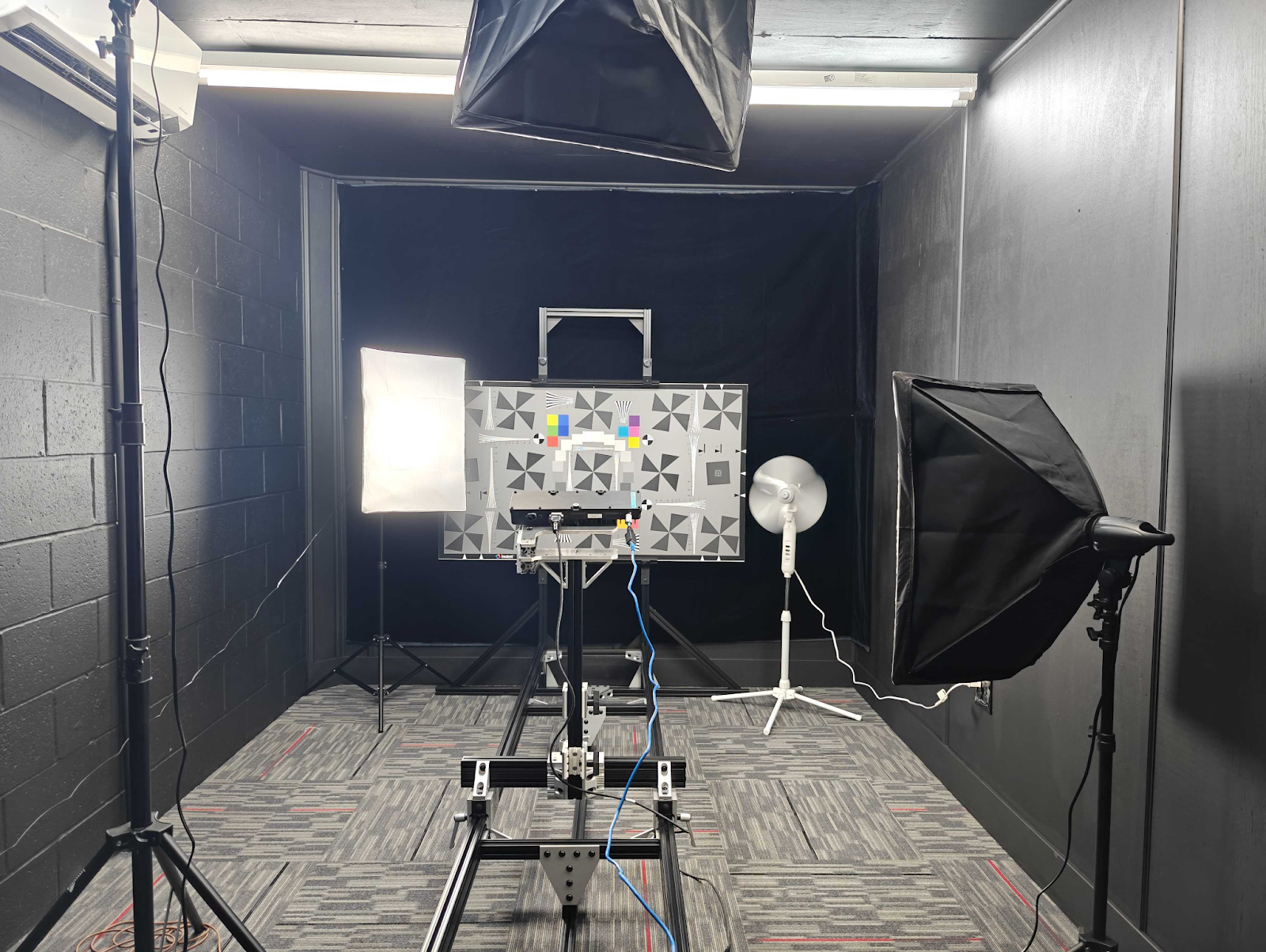
The time in microseconds for an image exposure. Making it longer brightens the image (good for dark scenes) and making it shorter darkens the image. For moving scenes, shorter is better because there will be less motion blur in the image.
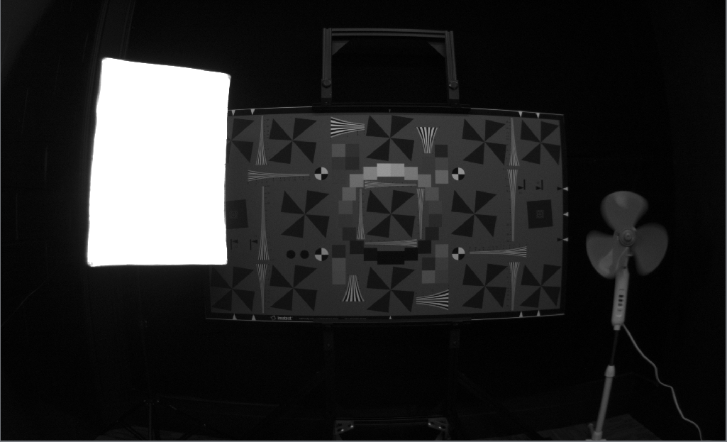
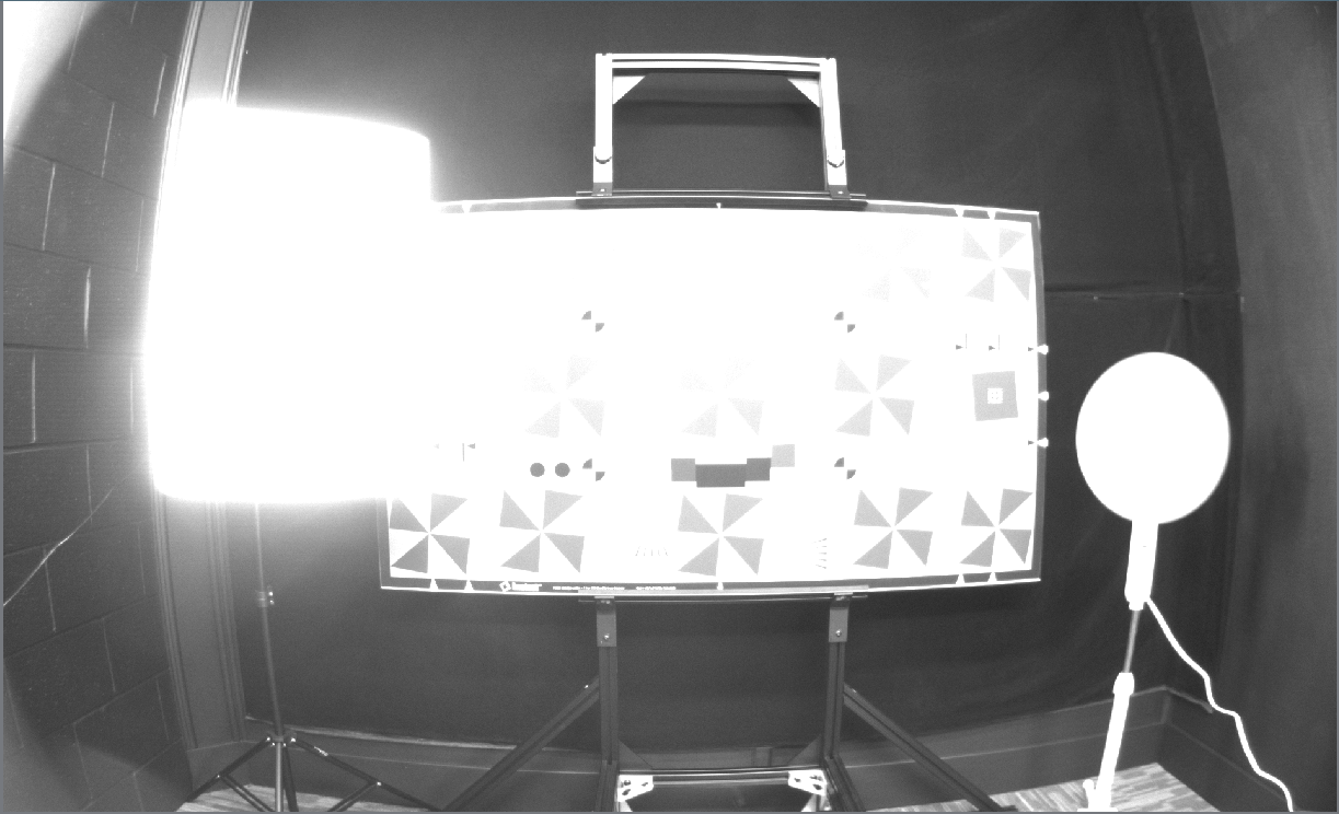
A 17,000 microsecond exposure. Notice that the fan is completely smeared.
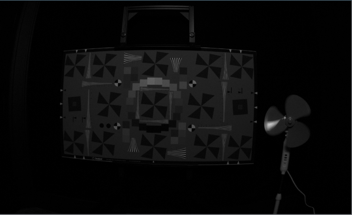
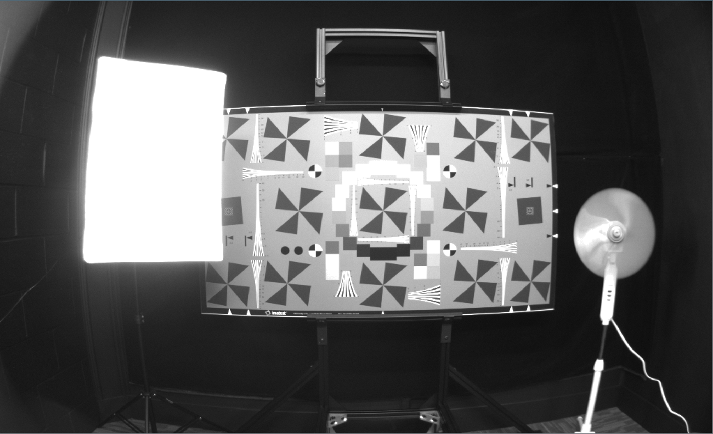
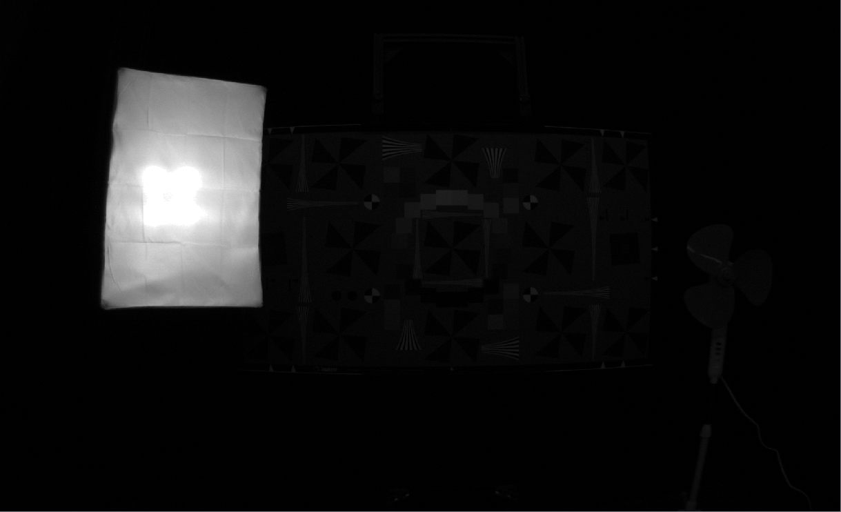
A 1350 microsecond exposure. Notice how the image is much darker, but the fan is much less blurry.
The gain setting brightens the image with a predetermined combination of electrical (analog) and mathematical (digital) gain. Increasing gain allows you to have a brighter image with the same exposure time, but increases the noise in the image.
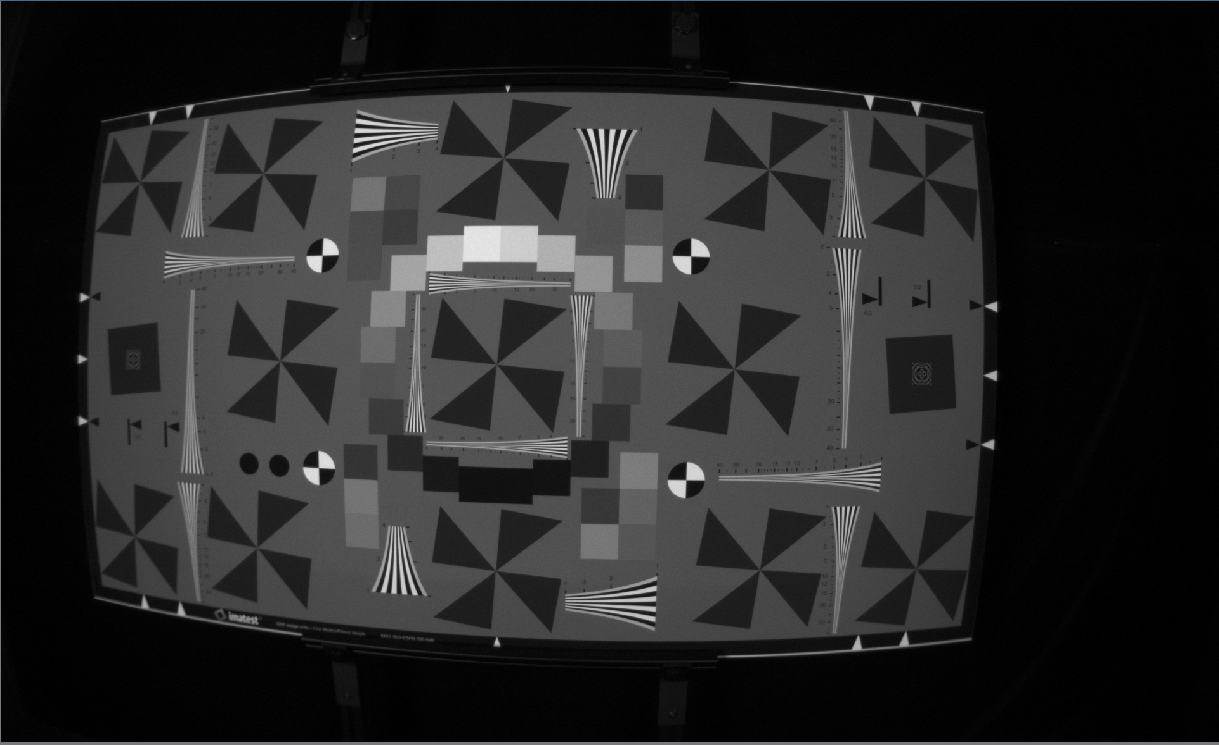
An image taken with 8000 microsecond exposure and gain of 2.0
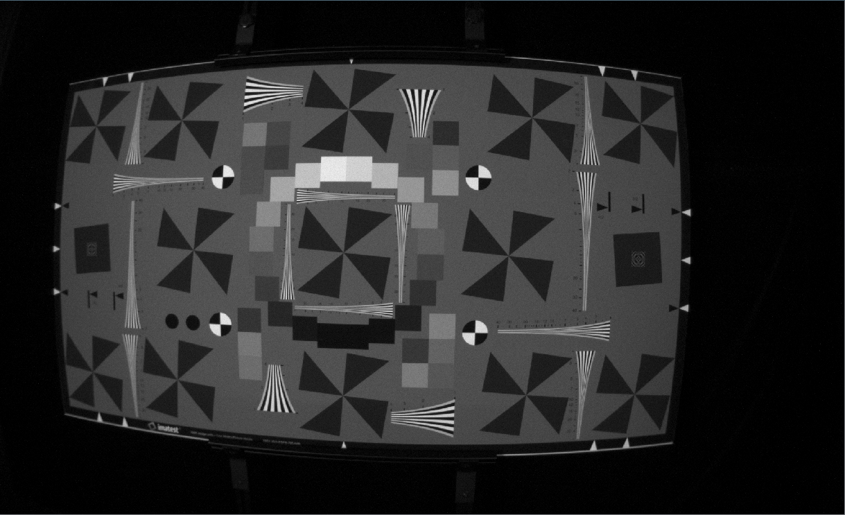
An image taken with an exposure of 2000 microseconds and a gain of 8.0. Notice the increased noise, which comes with reduced motion blur.
The autoexposure decay rage controls how many frames the camera takes to get the exposure right. In scenes where there are expected sudden flashes of light, it can be helpful to slow the autoexposure down
Autoexposure intensity and threshold parameters control the brightness of the image—what the autoexposure considers success. In a histogram of the image (where height is number of pixels and x-axis is brightness value) the autoexposure drives the exposure time until the threshold fraction of the pixels are below the intensity value. The camera defaults to intensity 0.5 and threshold 0.95, which means that the camera tries to make 95% of the pixels darker than 50% brightness. We do this to limit the number of pixels that become saturated in the image because saturated pixels have no information. Visually individuals tend to prefer images that have the threshold turned down below the default value of a bit, or that have the gamma Gamma turned up.
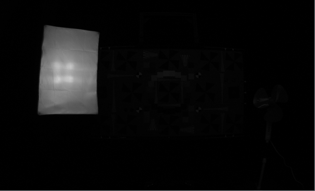
Intensity set to 0.1, threshold set to .885. The camera is attempting to make 88.5% of the pixels darker than 0.1 on a scale of 0.0 to 1.1
Intensity set to 0.9, threshold still at .885. The camera is attempting to make 88.5% of the pixels darker than 0.9.
Intensity set to 0.5, threshold set to 0.989. The camera is attempting to make 98.9% of the pixels darker than 0.5. In a high dynamic range scene like this, the autoexposure has to choose between seeing the detail in the light and seeing the detail on the target. This pair of threshold and intensity is an excellent strategy for limiting the number of saturated pixels in the image.
Intensity set to 0.5, threshold set to 0.6. This allows us to see some more detail in the extremely dark black velvet background, while allowing about 40% of the bright pixels to fully saturate.
A region of interest is defined four parameters (start_x, start_y, width, height) of a box in the unrectified image upon which the autoexposure operates. This is useful if a large portion of the image will contain the sky or will be blocked by the ego machine. The autoexposure will not use the data outside of the region of interest. Note that the region of interest horizontal values are on a range of 1-1920 and the vertical region of interest values are on a scale of 1-1200, even when the camera’s resolution is set to 960x600
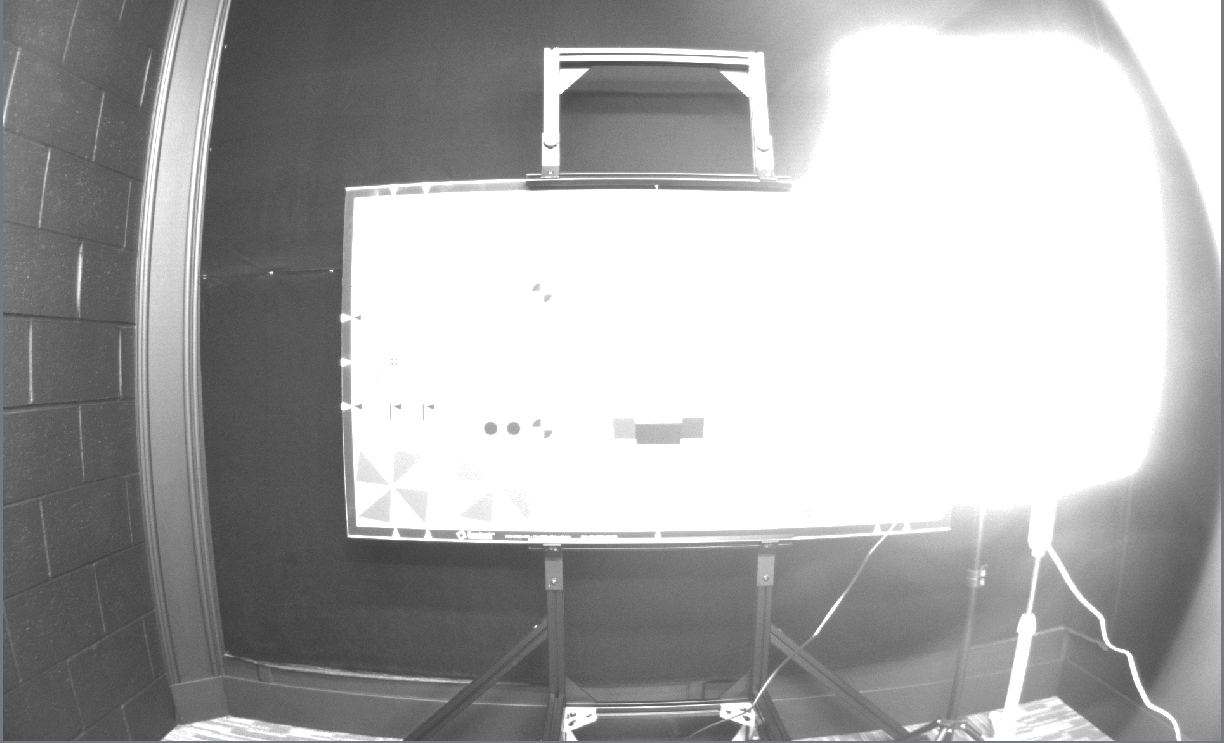
Here, the exposure is set to an intensity of 0.9 and a threshold of 0.885 as above, but with a region of interest corresponding to the photography light. Now, the only pixels used to control the exposure are the pixels within the region of interest.
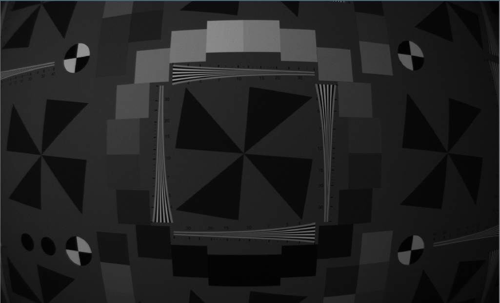
By moving the photography light out of the region of interest, the camera exposes well on the dark black wall, and the rest of the image is ignored (and therefore allowed to saturate.
The gamma parameter sets the gamma correction of the image. It’s an exponential digital gain that applies more gain to darker pixels and less gain to brighter pixels. If there are dark parts of the scene that you’d like to brighten without saturating bright parts of the scene, you can increase this. If you’d like the image to be more linear, decrease this.
This image, with a low gamma of 1.2, does not brighten the darker parts of the image, but instead gives a very linear response with the number of photons hitting the sensor.
This image, taken with a gamma of 2.2, digitally brightens the dark parts of the image without brightening the bright parts of the image. It can make detail in dark parts of the image more apparent, but makes the images appear to have less overall contrast.
Frame rate is the number of frames per second the camera outputs. There is something important to understand here: this is the output frame rate. The frame rate upon which the autoexposure operates is a whole number multiple of this frame rate near 30FPS. For example, if you set the frame rate to 9 FPS, the autoexposure will be correcting the image sensor at a rate of 27FPS. If you set the frame rate to 19 FPS, the autoexposure will operate at 19FPS.
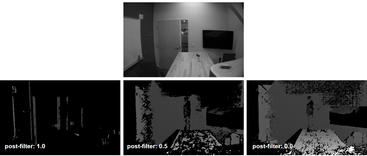
The stereo post-filter configuration filters the disparity image according to matching cost. A high Stereo Post Filter gives high confidence disparity images with very low density. A low stereo post filter gives a very high density disparity image with low accuracy and low confidence.
Resolution is parametrized by the triplet of (Width x Height x Disparities). The first number is the image width, the next number is the image height, and the last number is the maximum number of disparity levels. The disparity levels parameter affects the tradeoff between how far the camera can see and how fast the algorithm can run. Since we’ve done a bunch of work on increasing frame rates and for other reasons are limited to 30FPS, lots of these have a limit of 30FPS. The options are:
The number of IMU samples that should be included in an IMU frame. This parameter determines the batch size of IMU data packets sent from the device. Small batch
sizes combined with high sample rates will lead to increased processing overhead on the camera and is not recommended.
Each IMU sensor (accelerometer and gyroscope) can be independently configured with an operating mode. Supported configurations for each sensor are queried from the MultiSenseInfo and selected by their index in the supported modes table.
Note
KS21i requires the same output data rate to be configured for both accelerometer and gyroscope.
Enabled: Determines if the specific IMU source is active.
Rate: The sampling frequency and bandwidth configuration.
Sample Rate: The frequency in Hz at which the sensor is sampled.
Bandwidth Cutoff: The frequency in Hz at which the low-pass filter cuts off, impacting the signal bandwidth.
Range: The dynamic range and resolution configuration.
Range: The maximum value the sensor can return (expressed as +/- units for the given source).
Resolution: The minimum resolution the sensor can return, expressed in units per Least Significant Bit (LSB).
Configuration for the onboard accelerometer, which measures linear acceleration. The following tables list some example supported rates and ranges for one model of accelerometer. Querying the camera is required to get an accurate representation of available rates and ranges.
Configuration for the onboard gyroscope, which measures angular velocity. The following tables list some example supported rates and ranges for one model of gyroscope. Querying the camera is required to get an accurate representation of available rates and ranges.
MultiSense cameras provide flexible lighting control options, categorized into internal and external configurations. The support for these controls depends on the specific camera model:
KS21i: External LED control.
KS21: Internal LED control.
S30 with external lighting: External LED control.
Note
There must be an active image stream being published from the camera for the LEDs to turn on
External lighting controls are used for lighting systems driven by the MultiSense GPIO outputs. These controls were specifically added to handle the wide variety of performance characteristics found in external LED systems, ensuring optimal synchronization and illumination regardless of the hardware used.
Intensity: Adjusts the brightness of the external LEDs on a scale from 0.0 to 100.0.
Flash Mode: Determines how the external light flashes in relation to the camera sensors:
NONE: Disable flashing.
SYNC_WITH_MAIN_STEREO: The flash is synchronized with the exposure of the main stereo sensors.
SYNC_WITH_AUX: The flash is synchronized with the exposure of the auxiliary sensor.
Pulses per Exposure: Specifies how many times the light pulses for a single exposure. For values greater than 1, the pulses occur between exposures. This feature can be used to make the flashing less noticeable to the human eye while still providing high-intensity light during sensor exposure.
Startup Time: The duration (in microseconds) required for the external light to reach its full intensity. Configuring this correctly ensures that the light is at its peak brightness exactly when the image sensor begins its exposure.