5. Interface Specifications
5.1. Mechanical
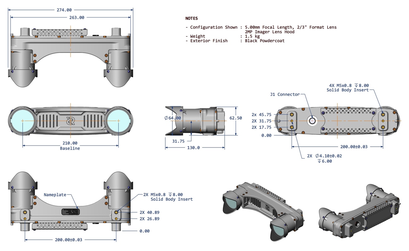
A downloadble PDF of this drawing and a simplified CAD model is also available in the table below.
|
|
|
5.3. Isolated IO
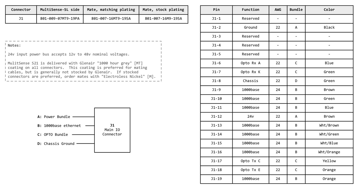
The MultiSense S21 has opto-isolated inputs and outputs. Currently, the input can be used as a 1:1 frame trigger and the output can generate a pulse-per-second signal (PPS). After generating a PPS pulse, the FPGA sends a PPS timestamp message to the connected client, see PPS Topics for more information.
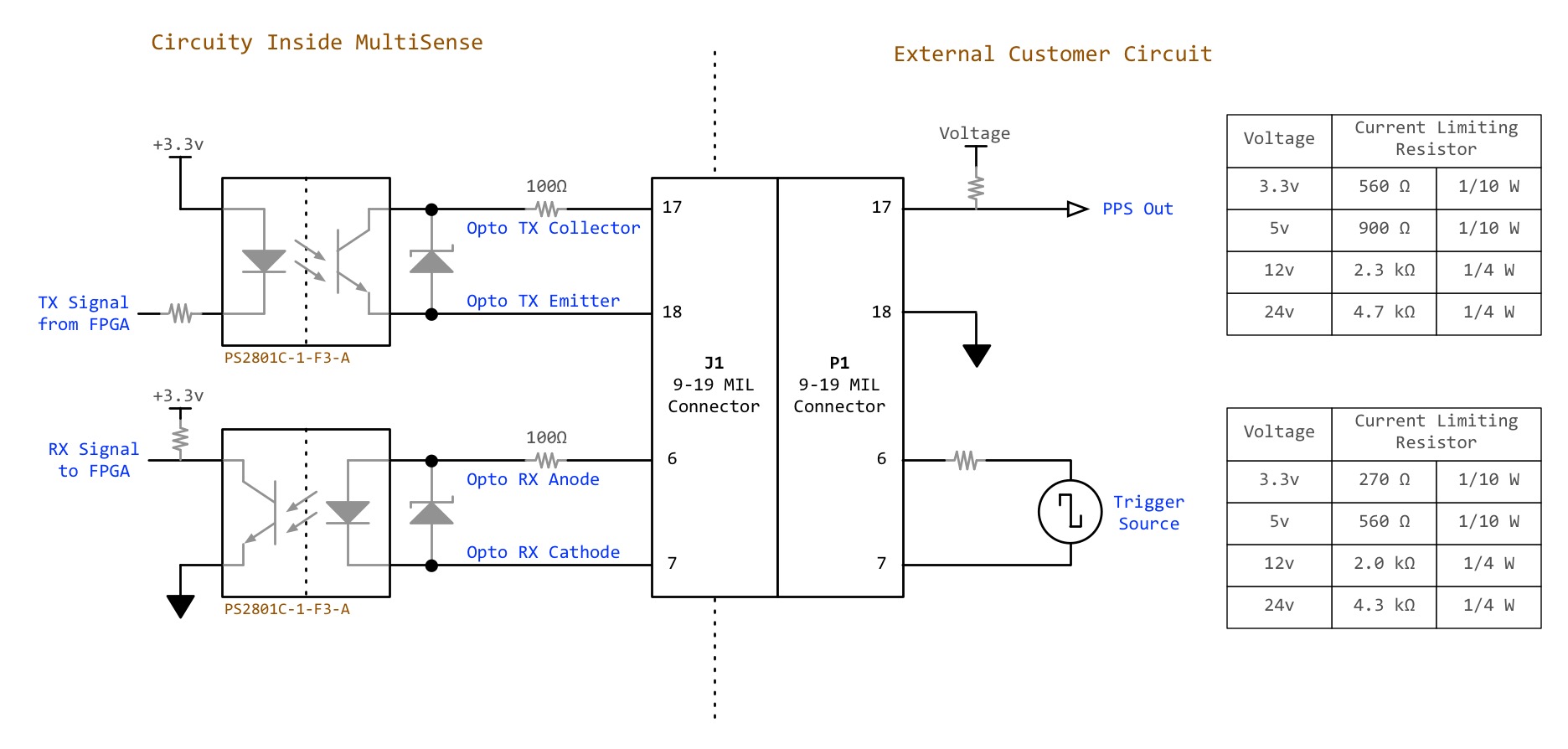
To correctly interface to these opto-isolated signals, certain external circuity must be connected to the MultiSense S21. The values of the external current-limiting resistors used must change depending on the external voltages supplied or desired. Please read the Opto-Interface Drawing for more details.
|
Direct connection to external voltage sources WITHOUT the specified current-limiting resistors may permanently damage the opto-isolated inputs and outputs of your MultiSense S21. |
|
The frame trigger has 400us of filtering on the rising edge and 10us of filtering on the falling edge and the falling edge causes the frame to be captured. This means that the system will not trigger until the trigger signal has been asserted for at least 10us (this is assuming zero bouncing) and that the trigger will not reset until it has been deasserted for at least 400us (again, assuming zero bounce). |
|
5.4. IMU
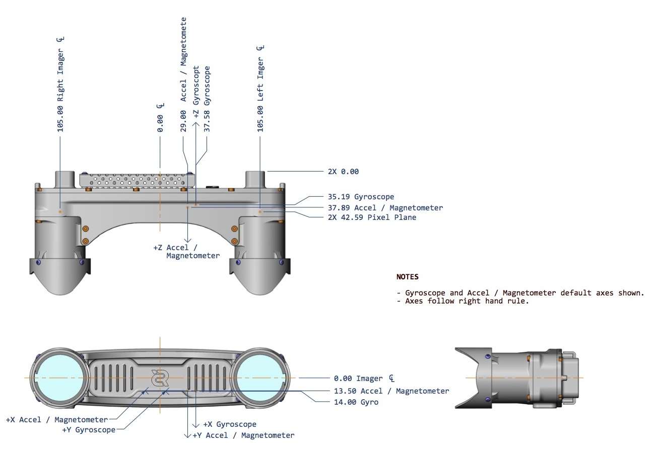
The accelerometer and magnetometer are mounted in the locations and orientations called out in the CAD drawing below. Their locations correspond with the /multisense/accel, /multisense/mag, and /multisense/gyro frames in the /tf tree.
|
"Stereo Origin" corresponds to |
|
|
|
STMicroelectronics LSM303DLHC, Accelerometer |
|
STMicroelectronics L3G4200D, Gyroscope |
Accelerometer
The accelerometer and magnetometer are combined on a STMicroelectronics LSM303DLHC 3-D linear accelerometer and magnetometer microchip. The measured outputs for the accelerometer and magnetometer are in units of g-force and gauss respectively.
Gyroscope
The gyroscope is a STMicroelectronics L3G4200D three-axis gyroscope. The measured output is in degrees per second.