Overview
Stereo cameras use a principle of triangulation to determine how far an object is from the camera. Simply put, the camera’s processor finds matching objects in the left and right images, and notices that they are in different positions at different distances.
Consider the following scene, which consists of a cardboard box and a fan, but the cardboard box is much closer to the camera than the fan. Notice how the cardboard box is shifted significantly in the right image compared to the left–it’s much closer to the left-hand side of the right image than it is in the left image. This is because the cardboard box is much closer to the stereo camera than anything else in the scene. The stereo camera has to “cross its eyes” more to connect to see the cardboard box than it does to see the fan. This shift in position we call “disparity”–a measure of how disparate the object’s position is in the two cameras. Notice that the bottom right image is called the “disparity” image. That image is a version of the left image, but where the brightness of the pixels is the shift in position.
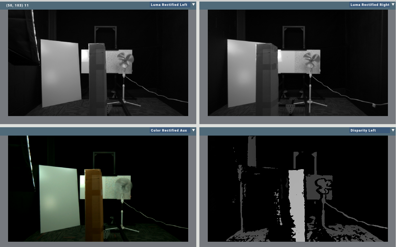
(Top left) left rectified, (top right) right rectified, (bottom left) aux rectified, (bottom right) disparity
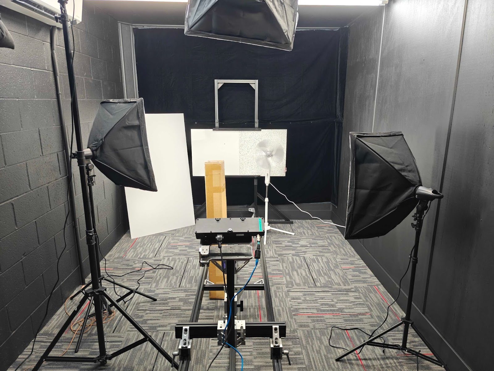
The above images were captured from the following scene
Using the calibrated geometry of the lenses, the dense disparity image can be reprojected into a 3D point cloud.
Texture
One of the important parameters for a stereo camera to function reliably is scene texture. This is the complexity and detail in the scene. Basically, a scene can never have too much texture or detail for a stereo camera. More is always better.
Consider the following pair of targets. On the left is a blank gloss white target and on the right is a speckled target. The disparity shows valid returns on the speckled target but not on the blank target.
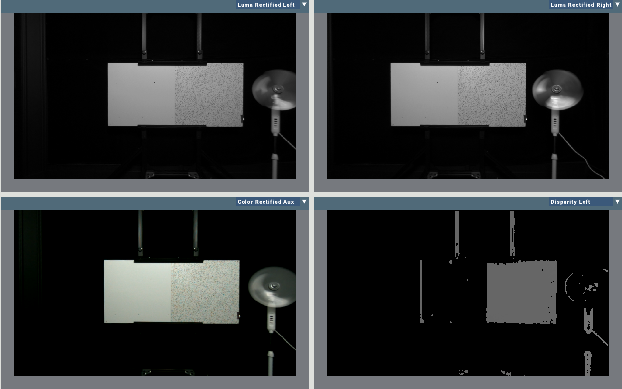
A disparity image generated from a blank target on the left and a speckled target on the right. Notice how the stereo camera is able to generate depth estimates for the target on the right, but not for the target on the left. This is because the visual texture of the right image gives the stereo matching algorithm something to compare between left and right images.
If the environment you intend to work in has very low visual texture, the camera can be helped along by the use of a pattern projector. A pattern projector is available on our indoor cameras and projects a dot pattern of invisible light (850 nm wavelength, the limits of human vision are around 700 nm), that the camera can see and use as texture.
Another way of dealing with low texture scenes is to reduce the Stereo Post-Filter configuration.
Reflections
The stereo algorithm operates on the critical assumption that all rays of light travel in a direct path. When specular reflections are present in a stereo scene, the algorithm may misjudge the distance of a reflected object. This presents itself as an artifact in the disparity calculation.
Observe the following scene that has been staged to demonstrate this effect.
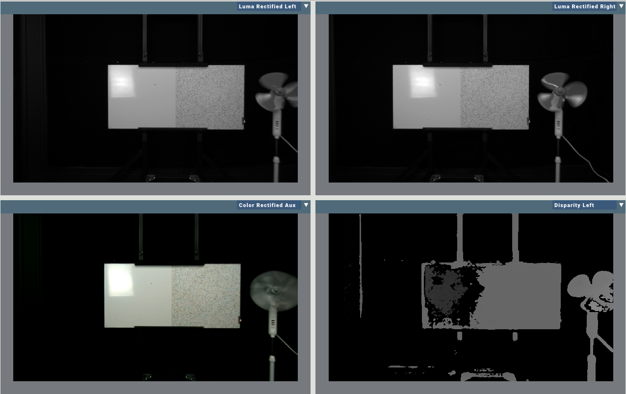
The above image shows a photography lamp positioned such that it appears as a reflection on the left side of a glossy target. The right side of the target has a speckled surface. We can see that the stereo camera is able to correctly calculate the distance to the right half of the target, to the edges of the target, and to the fan to the extreme right of the image. Importantly, the distance to the photography lamp is correctly calculated, but the position of the lamp is incorrectly placed deeper into the scene, through the surface of the reflecting target. This false object is the artifact of the algorithm.
Rectification
Rectification is the process of undistorting, rotating, and shifting the left and right images of the stereo camera so that they align with one another. This greatly simplifies the stereo matching, because it guarantees that features in the left and right images will occur on the same row of the image.
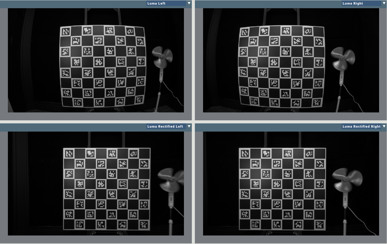
Here is an image of a checkerboard where all the white checkers have been filled in with unique tags. Notice how in the top row (the unrectified images) the target appears curved and rotated towards the center. The second row are the rectified images. Notice how they have been aligned with one another and the lines in the target have been straightened, just as they appear without the distortion of the lens. The rectification process does result in some amount of field of view loss, as the corners of the image get stretched out beyond the edges of the image. This field of view loss can be mitigated by changing certain calibration parameters of the camera.